Drive-train & Steering
Analysis 1
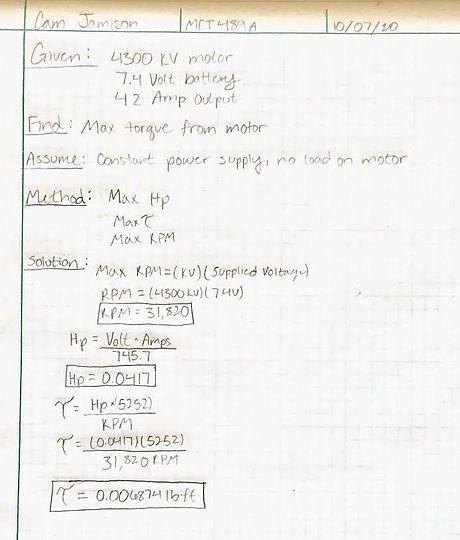
Max torque provided from chosen electric motor.
This analysis basis off meeting a minimum torque requirement of 0.006 lb.-ft. to ensure there will be enough power to be competitive during the ASME BAJA competition. A new drive train system has been chosen, but since this motor is still the driving system being used the analysis is still valid.
Analysis 2
Max Speed with given parameters.
The requirement of reaching a minimum max speed of 20 mph is the basis of analysis number 2. The max rpm from the driveshaft was calculated along with the rpm from the rear wheels, and the distance traveled per one tire revolution with the chosen tire size. Those calculation lead to a max speed calculation of 23.95 MPH. This will be considered a preliminary analysis since a new drive train system has been chosen. Instead of a drive line from the motor to a rear differential it will be a spur gear to a pinion gear for more efficient power supply and simplicity.


Analysis 3
Torque required to turn the wheels.
The axles need to withstand 25 kg/cm of torque per requirement, which is the reason for the analysis. The torque needed to turn the wheels was found to be 17.07 kg/cm which under the torque value stated. The appropriate axle size and material will be determined in the next analysis.
Analysis 4
Torque on spur/pinion gears
In appendix A-4 analysis 4 shows the calculation of torque applied to the spur and pinion gear from the motor and the transmission. This analysis assesses the requirement of the gears having to withstand the torque applied from the motor. Based on this calculations ABS plastic will be used for the spur and pinion gear.

Analysis 5
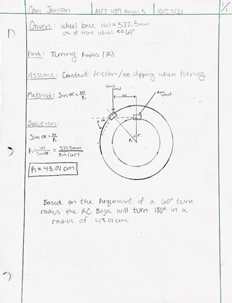
Turning Radius
Requirement:
Appendix A-5 analysis covers the requirement of at least a 60 degree turn radius.
Analysis/Design Parameter:
With a wheelbase of 372.5 mm the RC Baja will use 43.01 cm to turn 180 degrees. Based on this calculation the tie rod lengths and geometry are assumed.
Analysis 6
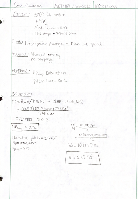
Average Horse Power
Requirement:
Analysis 6 addresses the requirement stating that the RC Baja should exceed 20mph.
Analysis/Design Parameter:
Appendix A-6 analysis is a calculation of the pitch line speed and average horsepower velocity. This calculation was done to see how much power could be sustained for longer periods of time and how fast it will come off the line for the drag race.

Analysis 7
Tie Rod Lengths
Requirement:
Analysis 7 addresses the requirement of having a turn angle of 60 degrees or less. The wheelbase length was found in a previous analysis. Knowing the overall length of the wheelbase along with wheel hub lengths allowed the Front Tie Rod lengths to be calculated for.
Analysis/Design Parameter:
The overall length of the wheel based is 372.5mm, the wheel hubs are both 28mm and the center link is 83mm. Knowing those parameters the length of the tie rods were calculated to be 92.75mm each. Aluminum is the chosen material for the tie rods.
Analysis 8
Battery Life
Requirement:
Analysis 8 addresses the requirement of the Lippo battery holding charge for the entire ASME Competition at least 20 minutes at full power.
Analysis/Design Parameter:
The 3800 KV motor was hooked up to the 7.4v battery and ran for just over 1 hour. In five minute increments the battery was tested with a voltage meter and documented. The 7.4v battery held charge for the chosen 20 minutes therefore meeting the design parameter.

Analysis 9
Required Fastener Size
Requirement:
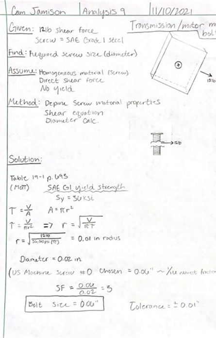
Analysis 9 addresses the requirement that the motor/transmission bolt must withstand at least 12lbs. of shear force.
Analysis/Design Parameter:
The material chosen for analysis was SAE Grade 1 steel which has a yield strength of 36000 psi. given those parameters a diameter of 0.02 in was needed to withstand a shear force of 12 lbs. The smallest size sold for a machine screw is 0.06 in, and that is the one chosen for the application.
Analysis 10
Shear Force on Pin
Requirement:
Analysis 10 addresses requirement number 5 stating steering arm pins must withstand at least 20lbs of double shear.
Analysis/Design Parameter:
The material chosen for analysis was 2011 T-3 Aluminum with a diameter of 1/8”. Yield strength for the chosen material is 32,000 psi. With 20 lbs. of shear force acting on the pin the average yield strength was only 815 psi, well below what the material is capable of handling at 32,000 psi. Therefore, the material will be used for the application.

Analysis 11
Steering Servo Angle
Requirement:
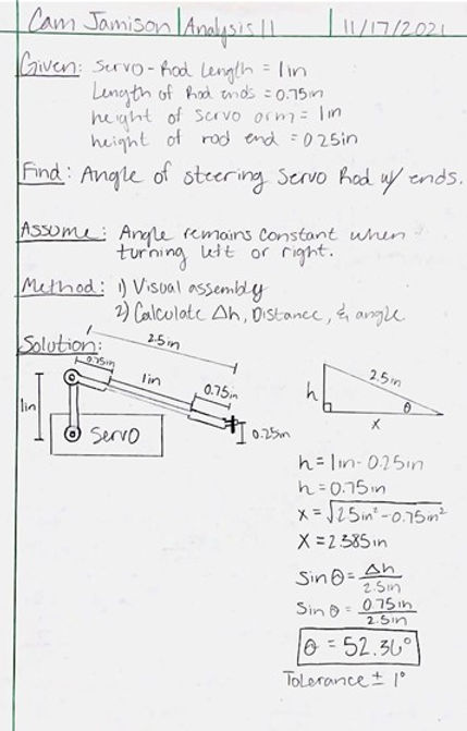
Analysis 11 addresses requirement 15 stating the servo rod angle must not exceed 60 degrees to make room for the front suspension tower.
Analysis/Design Parameter:
Based on the height of the servo arm and the location of the center link a geometrical calculation was made. The servo rod and rod ends were assumed, and the height and length were calculated to find the angle of the rod which came out to be 52.36 degrees which is under the 60-degree requirement.
Analysis 12
Diff Cover Fastener Size
Requirement:
Analysis 12 addresses requirement 14 stating the differential bolts must withstand 10lbs. of direct shear force.
Analysis/Design Parameter:
To tightly secure the differential housings together the bolt fastener size was calculated for based on steel grade 4.8 bolts from Mott table 19-3. A shear force of 10lbs. was assumed to be acting on the fasteners. Direct shear equation was used to calculate the diameter of the fasteners from the Mott bolt parameters in table 19-5. A diameter of 204 nm was found, so the smallest bolt size chosen from Mott was 1.6mm/M1.6.
